SIM900 Driver for KEIL MDK-Network (PPP interface for TCP/IP)
As promised before this post covers connecting a SIM900 module to the Network driver via PPP. The related Github checkpoint is available as a release here. The last commit can be used to get the code up to the point for this blog in case there are changes later. Let us now look at the magic elements, shall we?
First things first, I choose to use LPC4337 and the Cortex-M4 core. No particular preference, only that it was on my desk at the time I chose to write this post. Also, I bought this developer board here. The network driver is documented at length by Keil/ARM here, in case you need to familiarize yourself with it before proceeding.
There are 15 commits up to this one that show the steps on how code changed through the process.
Configuring the Network component
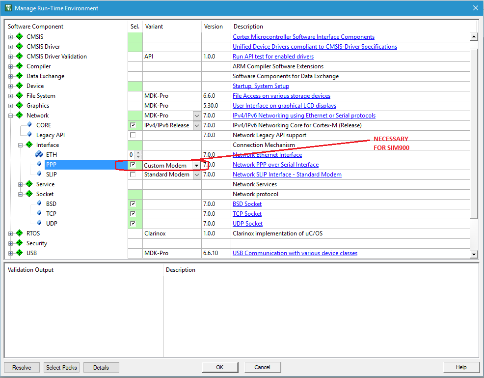
This is done by using the Manage Run-Time Environment window. Add the core API and add PPP under the interface section of the network. You will need to use the Custom Modem option so that we can customize for SIM900. It will be the same process in case you are using another cellular unit like the Telit ones. This now allows us to add a custom file that implements the modem driver logic. I took the Standard modem option provided by Keil and configured it to work for SIM900. The file is named Modem_SIM900.c
Adding PPP will require that a UART/USART driver be configured. We have three options:
- USART (use when your modem is connected directly to the microcontroller peripheral)
- USB CDC (use if the modem is connected via USB Host)
- USB PL2303 (use when connecting via PL2303 on USB Host)
You will also need to configure the services you need. I added the DNS client. In most cases, you will need all the three sockets available; BSP, TCP, and UDP. That’s my case as in the image.
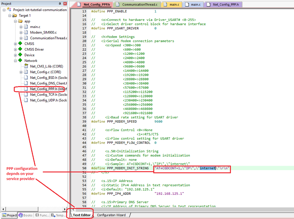
Once RTE is configured, head over to the Network group of your project tree and open the file Net_Config_PPP.h so that we can configure the elements of the modem. I used the configuration wizard tab to set the baud-rate. You can use it to configure DNS server, OS resources and number of retries to your taste or situation. However, if you have a special initialization string such as in my case, you will need to switch to the text editor mode. I used this to set the APN. The APN command is mentioned in a previous post so are the other commands you will find in the SIM900 file. The image below shows the result
At this point, your network is correctly configured. The only thing you need to know in advance is the dial-up number to call, username and password for login.
Configuring your RTOS
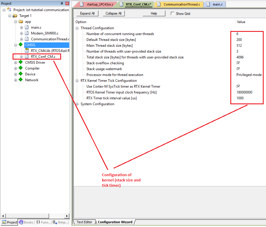
I used the already provided Keil-RTX because I find it easier to configure than any other I have used. Important things to watch for are:
- the processor speed must match the input for the SYSTICK timer
- the stack size for the main thread (sufficient enough to initialize the network stack)
- the total stack size and the stack size user-provided threads
Debug printout
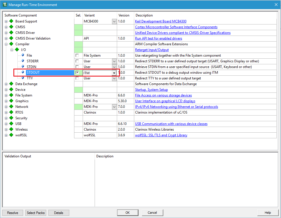
I prefer using SWO for my printf statements. I find it easier when I am not stepping through or when there is a component that needs to print out diagnostic logs. This is now easier to configure in the latest version of Keil than it was about a year ago. It is shown below.
Test program
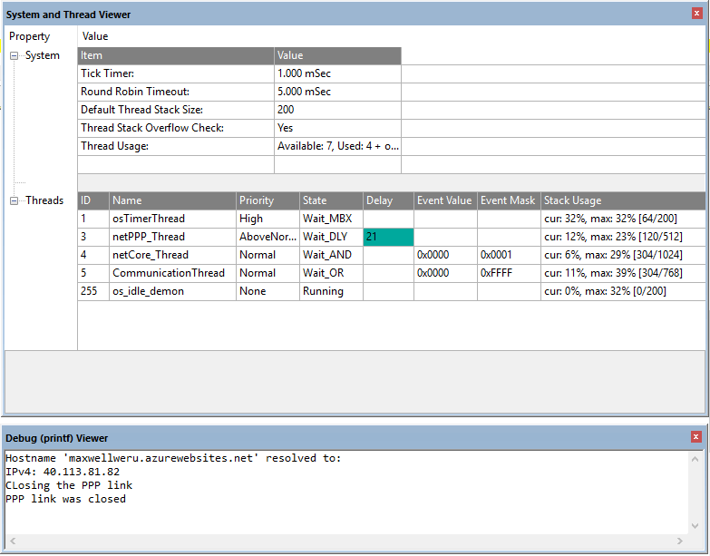
The easiest way I found to check if I have set up the network stuff correctly, is to resolve the IP address of a hostname. The reason being, it does not require you to set up any internet resources like a server. All I need is a domain (or subdomain) name. In this case, we resolve the IP address attached to this blog post in a thread separate from the main thread called CommunicationThread. It’s inside a file named CommunicationThread.c. In my program, I signal this thread after 5 seconds have elapsed on the main thread. This functionality can be replaced with any kind of interrupts like a button press, physical timer timeout or RTC alarm. It could also be periodic.
Results
I like to observe the OS Support dialog and the Debug (printf) Viewer dialog at the same time. I know it worked if I resolve the correct IP address. Yes! It works perfectly. (see image below)
Debugging
To see if you have set up everything correctly or in case you are having problems, connect a separate USB-UART bridge in “sniffer-mode” on the two comm lines for SIM900 (RX and TX). Then open a terminal and connect to that COM port. I use Terminal by braypp.
Your connection may result in two options: a) Acting as the micro-controller. RX from SIM900 goes to TX on the bridge, TX from SIM900 goes to RX on the bridge. This way you can send commands to SIM900 and receive responses. It helps debug if the modem is responding appropriately. b) Acting like SIM900. RX from the bridge goes to the TX on the micro-controller, TX on the bridge goes to RX on the micro-controller. This was you shall receive commands sent by the micro-controller. It helps debug if the microcontroller is sending the appropriate commands. If you use option (a) you should expect an output as shown in the image below. There is a lot of gibberish in the output but yes, it is okay.
In this example, the UART0 pins are mapped on P2_1 and P2_0 of LPC4337
Failures
There are reasons why your setup may not work. They include the ones below but the list is not a final one.
- The SIM900 is not powered on. Supplying power is not enough. You need to switch it own using the PWRKEY pin either using your micro-controller or the button on a breakout board.
- The antenna needs to be properly placed. I had to place mine close to the window since the place I reside in has varying network latency.
If there are others you find, let me know so that I can add them here.
Conclusion
In the next post of the tutorial, I will look at how to communicate something useful.